Engineering a Gravity Wall System Using Scourlok
Posted on 1.14.2022 by Drew Loizeaux, P.E.
Gravity retaining walls rely on the weight of the wall system itself to counteract the lateral earth pressures due to the retained soil. The most common gravity walls currently in use are comprised either of rock-filled gabions or of large concrete blocks, each weighing 1,800 lbs. or more (815 kg), that interlock together in a dry-stack fashion to construct retaining walls typically up to 12-feet high (3.6 meters). To reach such heights without additional artificial reinforcement, the offset distance for each layer may be increased and/or a wider (thicker) base section can be used on the bottom course to increase resistance to base sliding and to overturning moments.
In recent years, as site conditions allow, project designers have sought vegetated facing on these structures rather than traditional hardscape systems (i.e., concrete blocks or rock-filled wire-frame units). In response, SCOURLOK® was developed to provide a vegetated facing option using PYRAMAT® high-performance turf reinforcement mat (HPTRM), in conjunction with soil-filled, modular wire bastions.
Although the primary application for this gravity wall system is along stream channels and lake shorelines, it also can be used as a gravity retaining wall in non-water applications.
COMPONENTS AND CAPABILITIES
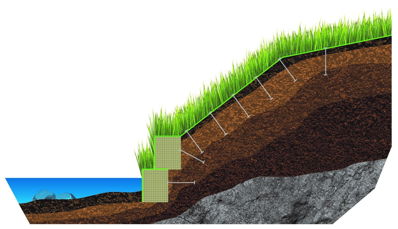
SCOURLOK is constructed of PYRAMAT 75 High-Performance Turf Reinforcement Mat (HPTRM) and interlocking, galfan coated carbon steel baskets lined with GEOTEX® Nonwoven geotextile. The vegetative pockets and tops of SCOURLOK are designed to be filled with organic growth media for vegetation. One SCOURLOK unit consists of 5 cells, each being 3 x 3 x 4 ft (L x W x H), creating a 15-ft long unit in total. The ends of the 4 ft high by 3 ft wide SCOURLOK units can be connected, forming a continuous structure, and stacked with an offset for various configurations. Each cell is open at the bottom and top, which allows ready setup and filling at the project site with on-site soil or granular fill. When several of these units are linked together in series, they form a gravity wall system. (Figure 1)
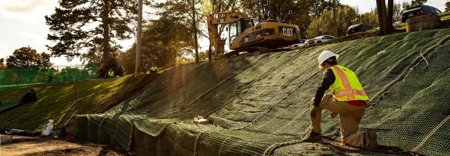
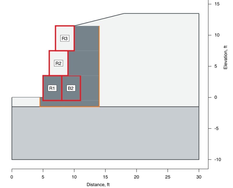
The SCOURLOK units can be shipped flat, then expanded out into the segmented units that can be stood up on a flat, prepared surface, then filled from the top with soil or gravel. The PYRAMAT wrap contains the soil and allows for seeds placed within the infill to sprout and grow through the HPTRM. It also provides sufficient tensile strength and UV resistance for excellent long-term performance of SCOURLOK walls. The units can be stacked on top of each other, using a setback distance of 0.5 to 1.5 feet, thus forming walls up to 12-feet high (Figure 2). Higher wall configurations may be constructed using a wider base, as long as the project specific design can provide an adequate factor of safety (FS).
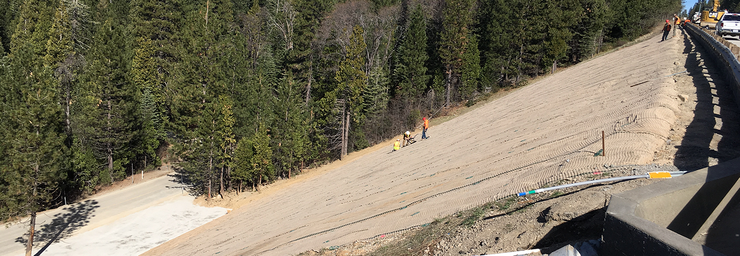
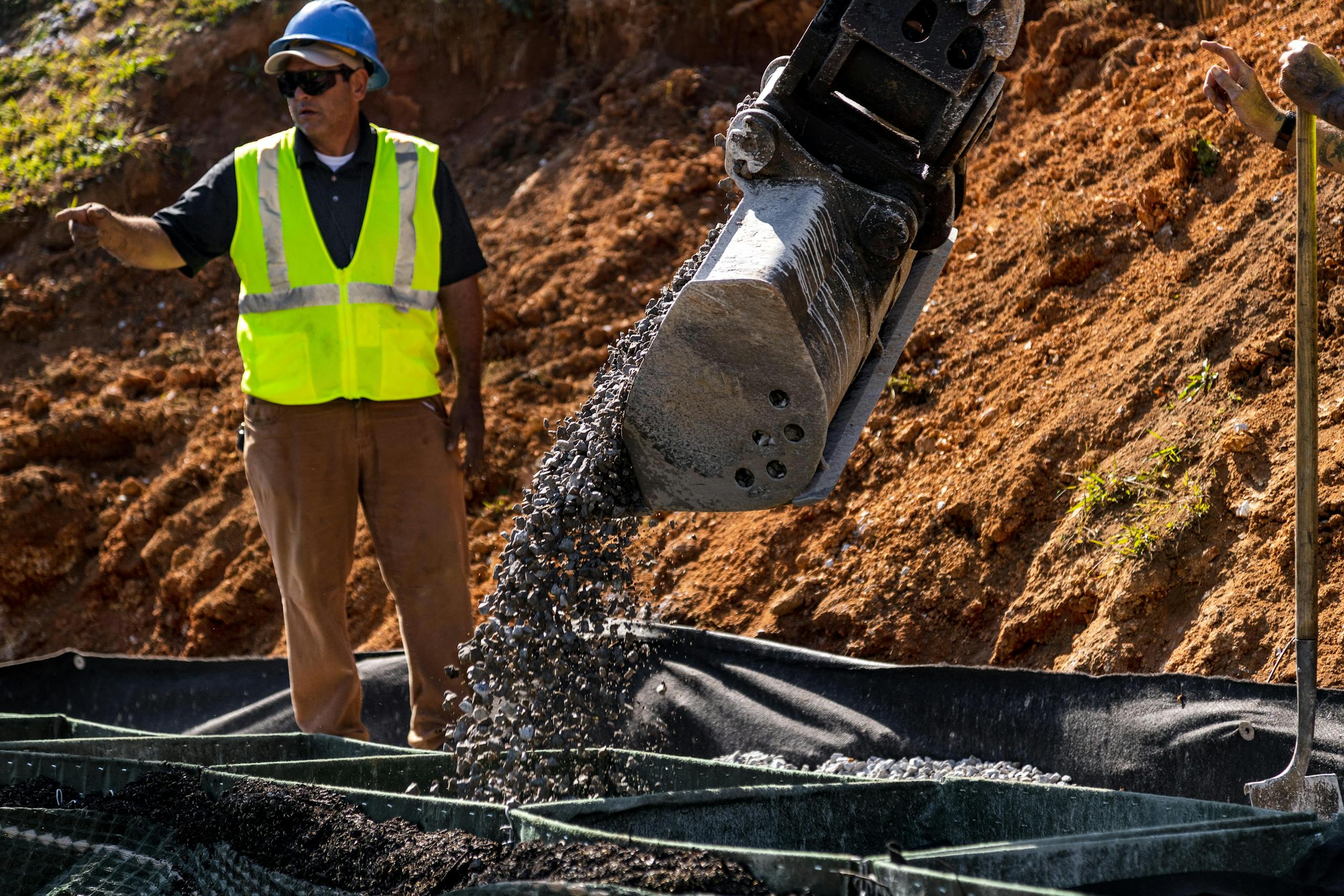
SCOURLOK walls must be founded directly on native soil or approved structural fill. In most cases, subgrade preparation involves using an excavator with smooth-blade bucket to remove topsoil and organic detritus to reach native, undisturbed soil and provide a smooth shallow trench to place the initial bastion row. If the foundation soil comprises clay or elastic silt, which are moisture-sensitive soils, then a compacted gravel leveling pad should be placed, along with a drainage system to remove excess groundwater at the base of the wall. If a foundation drain pipe is used, then it must have a proper outlet for water disposal or conveyance to low points. For sites prone to water submergence, the lower sections of SCOURLOK can be filled with coarse gravel to allow free movement of water without pore-pressure build-up (Figure 3).
It is recommended that soil infill for SCOURLOK meet the following specifications:
Classified as GM, GW-GM, SM, SW-SM, SC-SM, CL-ML, or ML referencing the Unified Soil Classification System (USCS).Contains maximum particle size of 3 inchesHas a Plasticity Index (PI) of fines not exceeding 10, Liquid Limit not exceeding 30.Has natural or conditioned moisture content to allow proper compaction Contains no deleterious substances (wood, metal, plastic, waste, etc.), hazardous chemicals, or pesticide/herbicide residue.
Because the SCOURLOK system is flexible, minor curves up to a 30-ft radius can be incorporated along the wall or slope alignment. This is achieved for each successive lift by flexing the units prior to backfilling. If sharper turns are needed, modifications can be made to the front or back panels of the individual cells in the field.
Soil compaction control during construction is critical to the long-term performance of these gravity structures. SCOURLOK infill should be compacted with a moderate effort, allowing some packing of the soil without causing excessive swelling of the cell walls. Compaction is required in the backfill zone behind the filled units. For small compaction equipment, such as vibratory plate compactors, the thickness of soil compaction lifts often is limited at 6 to 8 inches in order to achieve the specified density (per ASTM D 1557) Effective compaction monitoring and verification help reduce the potential for differential settlement, which may adversely affect long-term performance.
GEOTECHNICAL DESIGN CONCEPTS
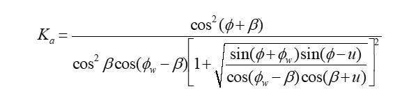
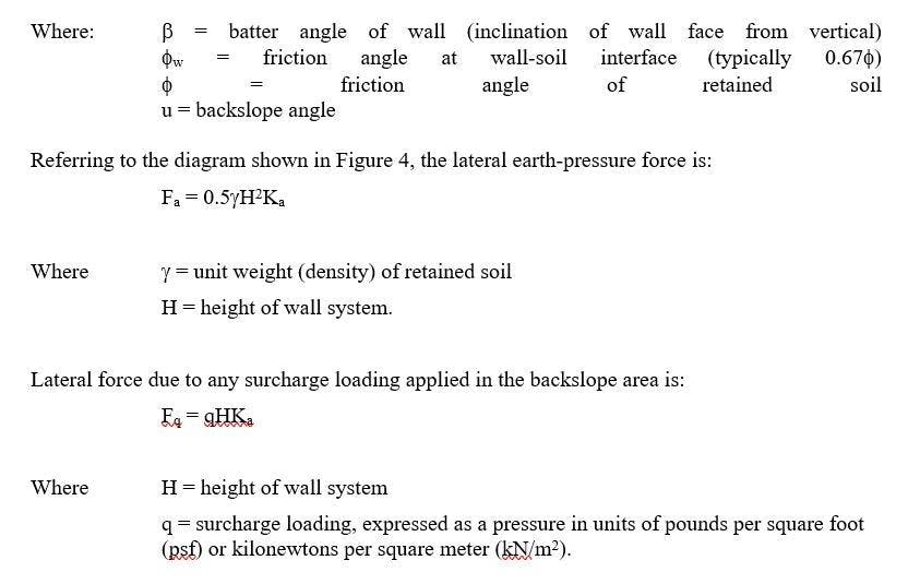
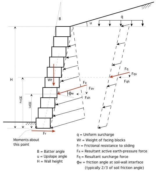
The weight of the SCOURLOK units must resist the lateral earth pressure due to the retained soil tending to deform and slide downward and outward due to the pull of gravity, as well as any lateral contribution from surcharge loading in the backslope area (such as permanent loads due to a building or bridge foundation or temporary loads due to traffic or construction equipment). The lateral earth-pressure force, Fa, (measured in force per unit length of wall face; i.e., lb/ft or kN/m) is estimated using the Coulomb active earth pressure coefficient Ka given by (NCMA, 1996):
These forces tend to overturn (rotate by tipping) the gravity-wall system or cause it to slide horizontally outward along its base; thus, they must be sufficiently resisted by the weight of the wall units to provide long-term stability. In addition, a bearing capacity analysis (foundation) and a global stability analysis (overall stability of wall and backslope area using a method-of-slices approach) can be conducted to evaluate these potential modes of failure external to the wall system itself. Optional ground anchors can be installed to form a “tie-back” system if local site conditions warrant. If a taller vegetated wall or slope is needed, then Propex’s PYRAWALL® system may be considered for the site (Miller, 2017).
Oftentimes, a coarse granular (crushed gravel) backfill zone is included directly behind the SCOURLOK units to allow free drainage of groundwater and to increase the friction angle along the potential failure path through the retained soil. Using a weighted value of the friction angle along this path (a path intersecting some gravel and some retained soil) results in a lower computed value of Ka, and thus, increased stability of the wall system.
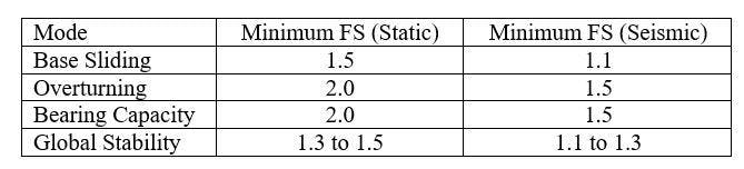
Geotechnical design criteria (i.e., factor of safety against failure) for the analyzed potential failure modes typically are prescribed as:
SUMMARY
By combining the PYRAMAT 75 technology with interlocking galfan coated carbon steel baskets and a GEOTEX nonwoven geotextile, an easily constructible gravity-wall system is now available for streambank, shoreline, and slope stabilization. Potential projects range from landscaping enhancements for residential and commercial properties to large-scale shoreline protection, as well as landslide repairs requiring a toe buttress.
For remote project areas or those heavily wooded or steep sites with difficult equipment access, the ability to easily transport or carry geosynthetic materials to the site is an advantage over heavier concrete blocks or metal panels. Remote sites along lakeshores, rivers, estuaries, or coastlines could be accessed by boat, readily transporting materials and workers to the projects. Once the leveling pad or foundation is prepared, SCOURLOK units can be rapidly deployed and setup, ready for soil infilling.
Note that site investigation and characterization of geotechnical soil properties are always required to provide reasonable confidence in the wall/slope design. Construction oversight and monitoring is strongly recommended to confirm the site conditions concur with those assumed in the design analysis and to verify that construction practices follow the engineering design and specifications.
REFERENCES
Miller, S.M. (2017). Versatile applications of internally braced, geosynthetic wrap-face vegetated walls and reinforced soil slopes. Geosynthetics 35(4): 24-33.
NCMA (National Concrete Masonry Association), Design Manual for Segmental Retaining Walls, 2nd Ed.; Herndon, VA, 1996.
Interested in PFAS-Free Plastics?